

Probably the most underrated aspect when it comes to designing a steel-to-concrete connection
Modern fixtures allow structures to transfer heavy loads, and these safety-relevant connections must be designed with precision. A widespread and consolidated approach when it comes to calculating a steel-to-concrete connection assumes that the anchor base plate does not deform under the influence of forces. Most likely, this is what you considered in all your previous post-installed anchor designs. As is the case with any other assumptions, this must be confirmed.
This post is inspired by a comprehensive technical dissertation on this subject published in Stahlbau (you can find the link to the reprint translation of the original German report at the very end of this page):
Fitz, M. , Appl, J. and Geibig, O. (2018), Wirklichkeitsnahe und vollständige Bemessung von Ankerplatten einschließlich der Befestigungsmittel – neue Bemessungssoftware auf Basis wirklichkeitsnaher Annahmen. Stahlbau, 87: 1179–1186. doi:10.1002/stab.201800036.
What does rigid anchor base plate mean?
In theoretical rigid anchor base plate behaviour, the load distribution is simplified by assuming that the plate itself does not deform analogously to Euler-Bernoulli’s beam theory. Strains are distributed linearly through the cross-section of the anchor base plate.
Under this hypothesis, the load distribution under the plate and the anchor forces are determined as illustrated in the next figure.

Figure 1: Reaction forces in the connection due to bending moment, tension
load or compression load with the assumption of a rigid anchor base plate
Let’s outline the three main consequences of incorrectly applying the rigid theory for an insufficiently stiff anchor base plate.
Consequence 1: Higher loads on anchors and higher stress on concrete
If, in contrast with the assumption, a flexible anchor base plate is used, this may lead to a reduction in the lever arm of the internal forces and thus to higher loads on the fixture, depending on the actual base plate deformation. The plate corners can become compressed against the concrete, inducing additional prying forces which, in turn, lead to an increase in the tensile force in the anchors.

Figure 2: The reduction of the level arm in a flexible anchor base plate
results in higher tension load in the anchors and prying force on the concrete
These prying forces will also be occur when a flexible base plate has an applied tension load, where the deformation of the base plate leads to significant overloading and premature failure of an anchor or group of anchors group.

Figure 3: In a tensioned flexible or rigid base plate anchor base plate, the prying forces
are equilibrated by higher tension load in the anchors
Also, in the case of a flexible plate under compression load, the stress distribution on the concrete under the plate might result in higher values than those calculated where rigid anchor base plate behaviour design is assumed.
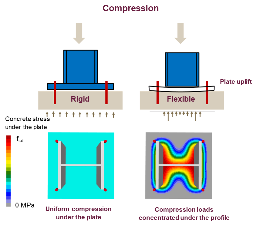
Figure 4: In a flexible anchor base plate in compression, the stress distribution results in higher concentrated loads on the concrete.
Consequence 2: Non-compliance with anchor design codes
In most international standards such as Eurocode 2 and ACI 318, resistance equations for a group of anchors are based on rigid anchor base plate assumptions only. Therefore, by using the formulas provided by these guidelines in the case of flexible anchor base plates, the anchor calculation can lead to inaccurate results. This is why the disclaimer for checking the rigidity of the plate is clearly stated in the anchor calculation report with the PROFIS Engineering software.
Consequence 3: Underestimated deflection in SLS
Flexible anchor base plates tend to exhibit larger deformation than rigid plates. For a cantilever beam, a flexible anchor base plate will result in larger displacement as there is more rotation in the anchor base plate. As an engineer, you should consider this in the SLS assessment, especially in cantilever and self-standing applications.
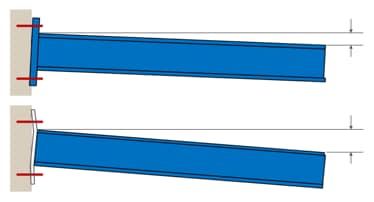
Figure 5: Displacement of the cantilever beam in the case of rigid and non-rigid anchor base plates
The solution
It should now be clear that assessing the plate rigidity is critical in terms of application safety. Despite this, no clear rules are available in literature on how to properly validate this requirement. Therefore, this step is generally omitted or only qualitative judgements on the plate geometry (e.g. ‘thick-enough feeling’) and stiffeners arrangement are considered.
Currently, FEM analysis is the state of the art for a realistic assessment of anchor base plate rigidity and for ensuring an adequate design of the full connection.
Now, with the Hilti PROFIS Engineering Suite it is possible to calculate plates taking into account flexibility and the real behaviour of plate module components. It provides a precise verification of all the components of a connection, combining the component method commonly used in steel construction with a powerful CBFEM finite element calculation.
We promise to elaborate further on this in future articles, but in the meantime, more information on the technical case and solutions can be found in the above-mentioned technical publication.
Share your thoughts or questions, or request for information about the brand-new PROFIS Engineering software, by leaving a comment.