
Save time, reduce errors, and confidently design façade support systems.
At Hilti, we're continuously pushing the boundaries of engineering productivity. The new Façade module in Profis Engineering is designed to help façade designers and structural engineers save time, reduce errors, and confidently design façade support systems to concrete – all within a seamless digital workflow.

Whether you're working on curtain walls, window walls, or other applications, the façade module supports you from the early project phases. The tool enables quick and intuitive calculation of anchoring the façade structure to concrete slabs and walls, reducing the time spent switching between multiple designs or relying on manual calculations. It also helps ensure installation tolerances are considered from the start – supporting efficient coordination between design and execution on the jobsite.

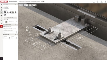
Figure 1: The new Facade module in PROFIS Engineering
Comprehensive Load Handling – Wind, Seismic, and Dead Loads
Modern façade systems in both low- and high-rise buildings must safely manage complex loads. The façade module supports the input of multiple combinations of wind, seismic and dead loads. By addressing all relevant loading conditions in one place, engineers gain more peace of mind that their designs meet safety and code requirements.
Design and optimize different fastening solutions at once
Anchor channels continue to play a vital role in façade engineering – offering flexibility for on-site tolerances and installation adjustments, especially in concrete cast-in-place scenarios. These tolerances are essential for compensating for deviations in jobsite execution.
The façade module makes it easy to design with Hilti anchor channels, post-installed anchors, or traditional solutions like embedded plates, all while considering eccentricities and geometric constraints that directly impact performance and installation feasibility. This leads to value-engineered solutions that help balance performance, efficiency, and cost – without compromise.
Jobsite specifications made easy
Comprehensive and clear report includes a clear communication of jobsite installation requirements, such as product item number, anchor and channels geometry and edge distance.
Compatibility with old PROFIS Anchor Channel designs
As the legacy PROFIS Anchor Channel software is phased out globally, all your existing anchor channel designs can still be accessed and edited within the new PROFIS Engineering platform.
For anchor channel design applications such as elevator guide rails, piping systems, cable tray supports and other MEP applications, Hilti has recently launched the new Anchor Channel module – helping ensure continuity and flexibility for all your projects. This module has been designed following the same exact flow than the one in the Façade module, so feel free to watch our Façade How to Video if you want to learn how to design your anchor channel applications.
Why Façade Designers Choose PROFIS Engineering
- Intuitive workflow tailored to façade applications, including Façade brackets and installation tolerances
- High-performance Hilti products tested to the highest standards, with third-party approvals (ETA/ESR) for transparency and reliability
- Code-compliant design for international standards (e.g., Eurocode, ACI)
- Visual feedback and reporting for better collaboration and documentation
The new Façade and Anchor Channel modules are opening compelling new opportunities within PROFIS Engineering. These modules stand out as one of the most substantial enhancements to our suite to date, expanding our SPEC2SITE offering by enabling value engineering for Curtain wall, MEP and elevator applications across multiple markets.
Here are some tips to help you get started today!
All the tips below are made specifically for the Façade module but can also be used within the Anchor Channel module.
Getting started with a new design and connecting to the relevant project
In the Façade module, at the top of the screen select “Settings”, introduce the “Design name”, and connect it to a “Project”.
To select the location of the project, select a project on the list or select “Create new Project”, naming it per your preference. Then click on “Save”.
Start with your typical applications

On the Application tab select the type that best fits your jobsite conditions. Applications on the top of slabs, face of slabs or even corners of the buildings are possible to design.
If you wish to design an application which is not covered, for instance on the front of a wall or bottom of a slab, it’s possible to directly adjust the pre-defined dimensions on the 3D.
Choose the most appropriate product for your jobsite conditions

On the application tab select the fastening technology. Multiple fastening technologies can be selected at once: cast-in anchor channels, post-installed anchors and embed plates.
Note that for the time being the corner application types are only possible with cast-in anchor channels. If you need support to calculate such applications, do get in touch with our engineering team.
To visualize the portfolio in your region, then move on to the product tab. The portfolio displayed is pre-selected to the relevant fastening technology.
In case of anchor channels, the portfolio is a combination of the anchor channel and the T-bolt. In Eurocode design, with HAC-V-30, it’s also possible to apply an internally threaded wing nut on the T-bolt.
Bracket geometry and load eccentricity
The façade bracket geometry can be input in the 3D model. The different bracket options consider different points of load introduction, to simulate jobsite conditions can be selected in the loads tab.

No plate
Loads must be introduced per bolt or per anchor

Base plate
Loads are introduced at the center of the plate and no lever arm is considered


Brackets
The load is introduced with lever arm. The point of applied load is described as the origin of the axis in the 3D model


When the plate or bracket is fixed directly to the concrete without an intermediate layer, in the plate tab select “No standoff”. In this case, the fixture is in contact with the channel and the concrete surface.
If there is a gap between the plate and the anchor, select:
- Standoff with mortar – when using a levelling mortar between the plate and the concrete surface. The shear load acts with lever arm, but the compression forces are still transferred to the concrete via the fixture.
- Standoff with bracket support – the fixture is fastened to the anchor channel with a lever arm.

In the case of slotted holes where a serrated washer is used, an additional lever arm may be considered in the direction of the slot. The length of the slotted holes can be adjusted by going to the loads tab and selecting tolerance in the slotted holes in the y-direction.


When selecting a tolerance, the calculation automatically calculates several positions of the bracket in relation to the anchor channel / anchor final installation positions. As an example for a top of slab bracket, the following tolerances can be considered.
Tolerance in channel length (x-direction)
Tolerance in/out (y-direction)


The utilization results are published for the most unfavorable tolerance. This position corresponding to the most unfavorable tolerance is displayed in the results pane and in the first page of the report.
All the failure modes are displayed for the most unfavorable position.
Calculate at once load combinations of static and seismic loads
The loads acting on Façade brackets are typically combinations of self-weight, wind pressure, wind suction and, in some cases earthquake loads.
It’s possible to calculate multiple load combinations at once and import the load combinations from an excel spreadsheet.
Note that it’s important to define all the load combinations which correspond to seismic load cases.
Export clear design reports
Use the report feature to document your design, including input assumptions and code checks - ideal for submittals or internal reviews.
For more information, check out the Profis Engineering software Facade module at Hilti PROFIS Engineering
If you have any questions, feel free to reach out to your local Hilti engineer for support at NZengineers@hilti.com